Q volume flow capacity m 3 s gpm cfm n wheel velocity revolution per minute rpm d wheel diameter.
Centrifugal fan impeller design calculation xls.
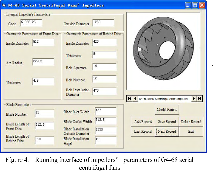
Report of design data.
25 m 3 min of gas i e.
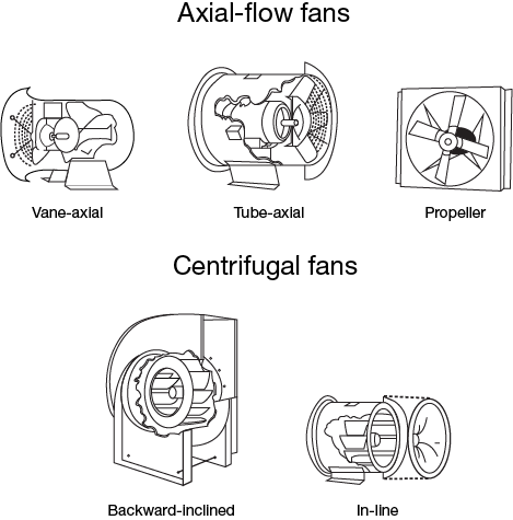
Backward inclined airfoil forward curved and radial tip.
Pdf doc xls jpg gif tif png fax etc.
The highest efficiency of all of the centrifugal fans.
Centrifugal er design calculation xls.
Whats people lookup in this blog.
Depending on the number of blades designed for each fan the total impeller grid was approximately 3 to 4 million cells.
The highest speed of the centrifugal fans.
The corresponding volute for each fan had approximately 1 5 million cells.
Detail drawing of shafts and hubs.
In line tubular centrifugal.
During this process stage velocity pressure and discharge at different stages are calculated.
Centrifugal fan types are.
Download free mep calculation excel sheets autocad drawings and training courses for hvac firefighting plumbing and electrical systems design.
Download fan static head excel sheet calculator.
All of these documents can be easily customized printed emailed or exported to formats like.
Some general types of the centrifugal pumps are as below.
Casings are generally of two types.
Assembly drawing of the fan.
Radial blade or radial tip.
Centrifugal fan impeller design calculation xls.
The head or pressure of a centrifugal fan can be expressed as.
538 8 r and 14 7 psi absolute with a discharge pressure of 0 3317 psi 250 mmh.
And handle 882 75 c f m.
Centrifugal fan design calculations xls.
The impeller inlet area should be no less than the inlet area of the blades.
With particular regard to centrifugal fans.
Spread sheet for the total head of fans and duct and fitting pressure drop.
The impeller design and the shape of the casing determine how liquid is accelerated though the pump.
Q 1 q 2 n 1 n 2 d 1 d 2 3 1 where.
The volume flow capacity of a centrifugal fan can be expressed as.
Calculation report of sound spectrum.
The grid topology used for the impeller design calculation shown in figure 5 was maintained.
The impeller is mounted on a rotating shaft and enclosed in a stationary casing.
Centrifugal fan design odologies dust collection research er centrifugal pump impeller design excel you free impeller and pump design software miscellaneous caeses forum.
Centrifugal fan design methodologies studies on radial tipped centrifugal fan 112 after inlet duct.
π øᵢ 4 π øᵢ.
Design calculation of the proposed impeller the centrifugal blower for gasifier is to run at 2500 r p m.
Energy balance is established at fan inlet intermediate stage of impeller and outlet stage of volute scroll casing.
Irrespective of design criteria an impeller s aspect ratio should ensure that its airflow is not compromised.